How to show a Deformed Shape as an Alternative Position View in a SOLIDWORKS Drawing

Article byMehdi Rezaei, CSWEupdated May 4, 2018
Article
在部分或装配环境中我们可以显示deformed shape of a model, fromSOLIDWORKS Simulationanalysis results, alongside the original model before the load was applied, an example is shown in the figure below. However, if you need to show the deformed shape in a drawing in order to add dimensions measuring maximum deformation it does not seem to be possible?
In this blog article, a workaround is shown using an Alternative Position View, which is used for assembly drawings, to show both unloaded and deformed shapes of a simulated model in a drawing.

Deformed Shape in Part Level along with Unloaded Shape
Save a deformed shape
The deformed shape of a model can be saved as another part file or configurations under the same part file. The saved deformed shape can be a solid body, tessellated, surface, or mesh.
To save a deformed shape, you need to right-click on the results and select “Create Body from Deformed Shape…”. Then, any above formats could be saved as needed.
For this article purpose, I have created two configurations for solid body and tessellated model of the deformed shape.

Create Configurations of Deformed Shape
Create Configurations for the Drawing View
Now, as the alternative position view is only available for assembly drawings, I need to insert the part model into an assembly. Then, I need to create a configuration in the assembly file for each deformed shape, the same as the configurations in the part level. Then in assembly file, at each configuration the corresponding configuration from part level should be selected to show.
In the following image, three configurations of a cantilever are shown in an assembly file where default and deformed shapes are assigned from part level configurations.

Part Level Configurations are assigned to Assembly Level Configurations
Then, this assembly model needs to be inserted into a drawing sheet.
Apply an Alternate Position View
Next, the Alternative Position View command can be used to show an existing configuration of an assembly on top of the drawing view.

Alternative View Is Used to Show an Existing Assembly Configuration in Drawing View
在下面的图片,提示deflectio的角n and also the maximum deflection of a cantilever is demonstrated in drawing view.
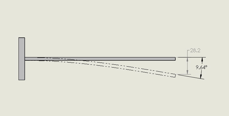
Deformed Shape from the Simulation result is shown as an Alternative Position View
Change display style of the alternate position
The display style capabilities of alternative view can also be applied here. To change the display style of alternative view, the drawing view must be must be found and expanded under the feature tree. Then, while having Alternative Position selected, the required display style could be assigned for the deformed shape. In the following image, the alternative view is shown in shaded mode.

Alternative View can also be shown in Shaded or Wireframe Mode
Related Links
Get Certified SOLIDWORKS Services from Javelin
Javelin Experts can help you to: