Simulate Welding in SOLIDWORKS with Weld Edge Simulation

Article byMalak Souissi, CSWPupdated April 20, 2023
Article
SOLIDWORKS simulation encompasses two types of edge welds:Fillet WeldandGroove Weld, which may be single-sided or double-sided to simulate welding. Fillet weld is a triangular welding technique utilized to connect two metal parts at a right angle. In contrast, groove weld is implemented in a pre-made opening or groove. The outcomes ofEdge Weldsare computed for all mesh nodes situated on the intersection of the terminated part’s edge. These outcomes are established with reference to a local coordinate system introduced at each node, as depicted in the figure.
下图显示了短小的代表d size. In the case of a fillet weld, the weld size is the measurement between the root and its toe, while the weld throat is the minimum distance between the root of the weld and the weld face. Concerning groove weld, the weld size is the width of the weld coverage, and the weld throat is the depth of the groove filled with weld.
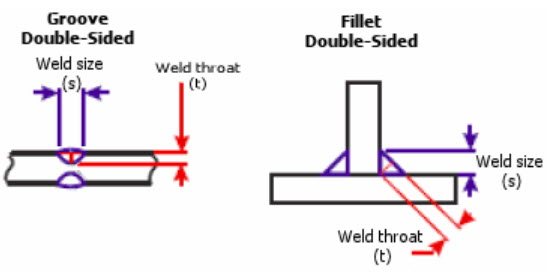
Weld Size demonstrated in SOLIDWORKS Help
The edge weld connector determines the necessary size of the weld required to connect two metal components. The software computes the appropriate weld size at each mesh node position across the welding seam. You may choose either American or European Welding Standards to conduct the welding calculations.
Note: The Edge Weld Connector is available inSOLIDWORKS Simulation ProfessionalandSOLIDWORKS Simulation Premium.
Example of Estimating Weld Size
Let’s examine a cantilever beam with four edge welds at its fixed end. It’s worth noting that surface bodies were used to model the beam to enable the inclusion of edge welds. To function properly, at least one of the two sides of the edge weld must be a surface body.
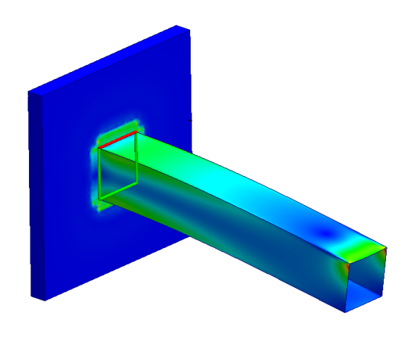
A Cantilever Model with 4 Fillet Edge Welds on the Fixed End
After completion of your welding simulation, to determine the size of the welds, you can right-click on the Results folder and choose “Define Weld Check Plot.”
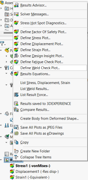
To Check on the Weld Size Estimation, Right-click on Results folder and Select “Define Weld Check Plot…”
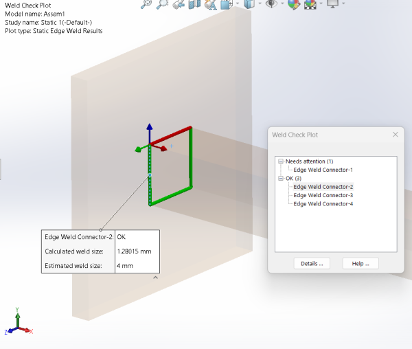
Edge Weld that needs attention in the model
You also have access to further details regarding the individual edge welds, by clicking the “Details” button on the small window.
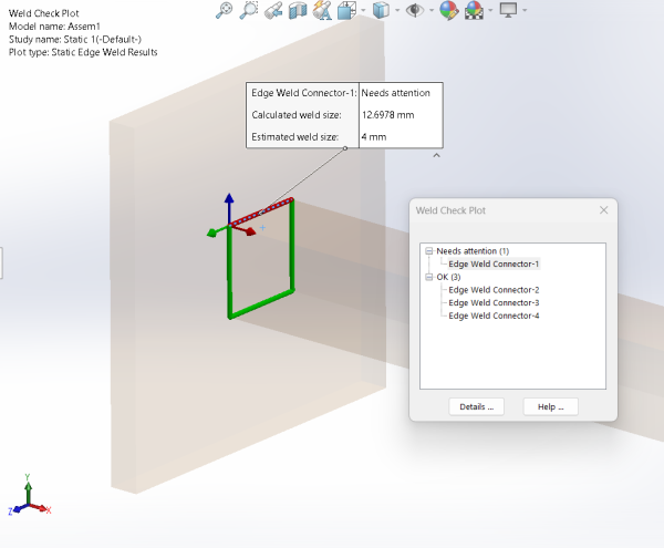
Details of the Edge Welds
We can also plot Weld Size (mm) vs. Position along weld seam distance to give even further insight into how the weld will be acting in real life, see the graph below.
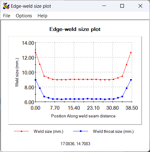
Edge Weld Size Plot vs Weld Throat Sizes
SOLIDWORKS Simulation Professional is a powerful tool you can leverage to simulate welding and iterate your design for the best outcome possible. Contact TriMech for more information about the tool.
Related Links
Get Certified SOLIDWORKS Services from Javelin
Javelin Experts can help you to: