P&ID
Schematic drawings are a universal method for detailing the connections between different components in electrical, hydraulic, and pneumatic designs. However, they are also a great way to communicate details of process flow or piping and instrumentation design. Our blog often touts the benefits of SOLIDWORKS…
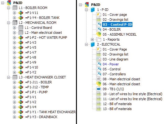
SolidWorks Electrical Piping & Instrumentation Diagram (P&ID) – Part 2

As discussed in Part 1, SolidWorks Electrical Schematic bridges the gap for 2D that is required in a Piping & instrumentation diagram. Instead of wire connections, users can create new wire style groups to show hydraulic or pneumatic type of connections. Different colours, sections, and…
SolidWorks Electrical Piping & Instrumentation Diagram (P&ID) – Part 1

Piping & Instrumentation is an important part of engineering design in some industries. Piping is already addressed in the SolidWorks Routing add-in. Now with SolidWorks Electrical Professional, we have the combination of Electrical Schematics, P&ID and Routing which makes it easier for engineers to efficiently increase design productivity. Start in 2D with SolidWorks Electrical In…